Microfluidic Device
CAD Model
Figure 1: Pinched Flow Fractioning Diagram (Yamada et al. 2004)
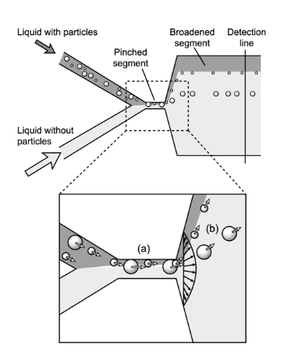
Figure 2: Dimensioned Drawing
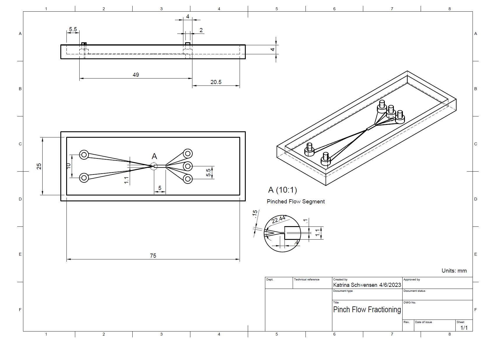
Figure 3: Model cast in PDMS
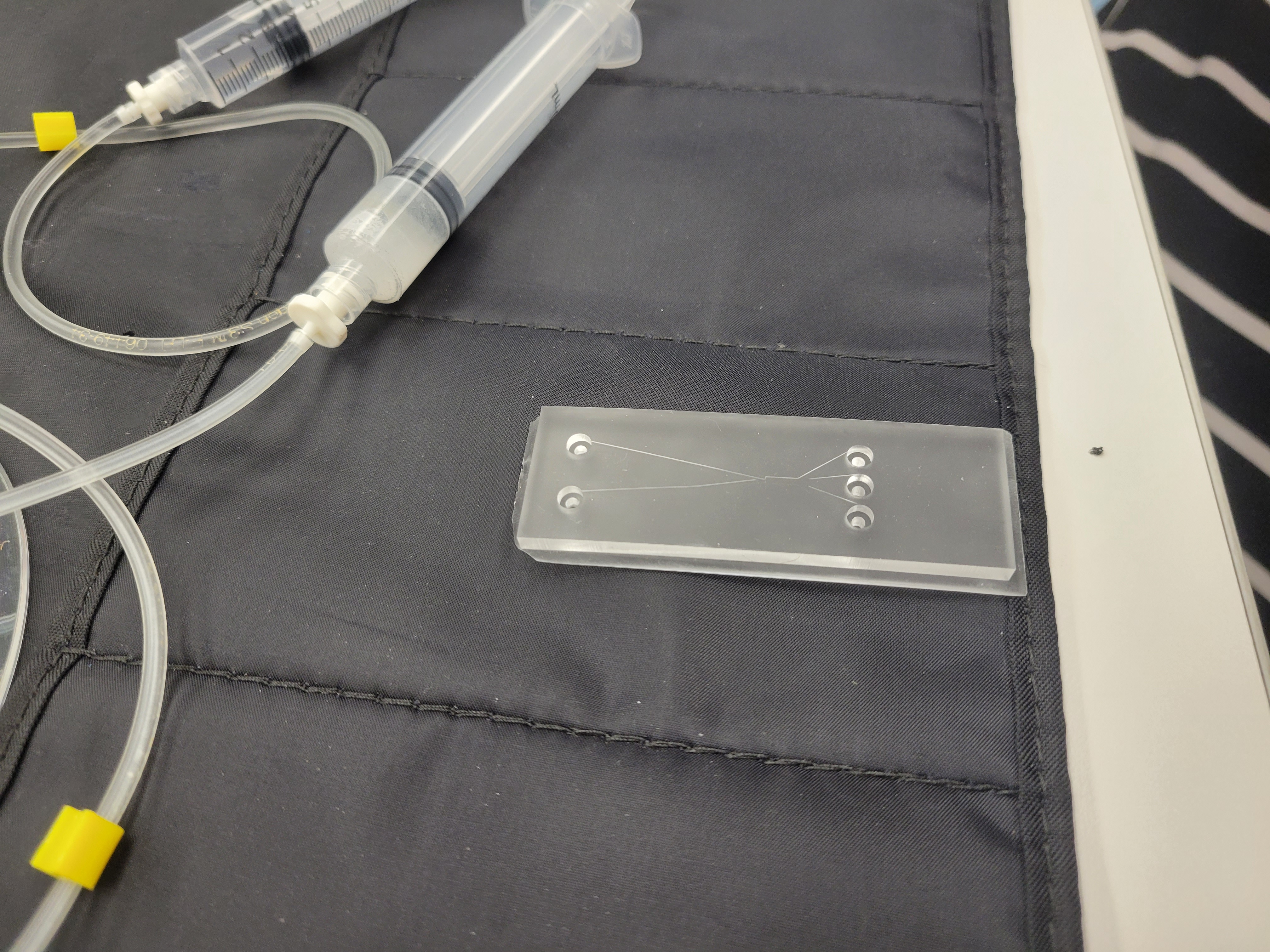
Figure 4: Testing Apparatus
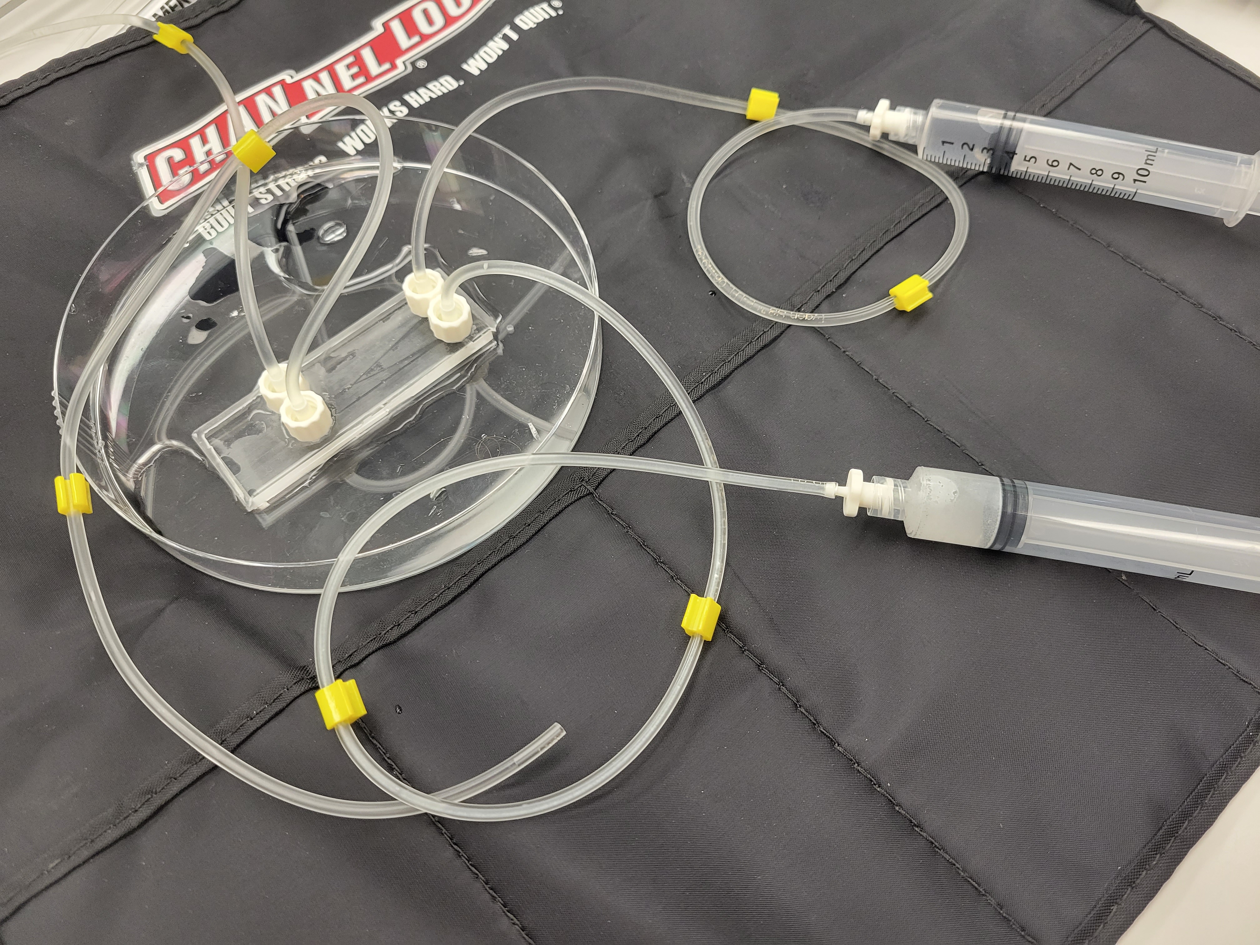
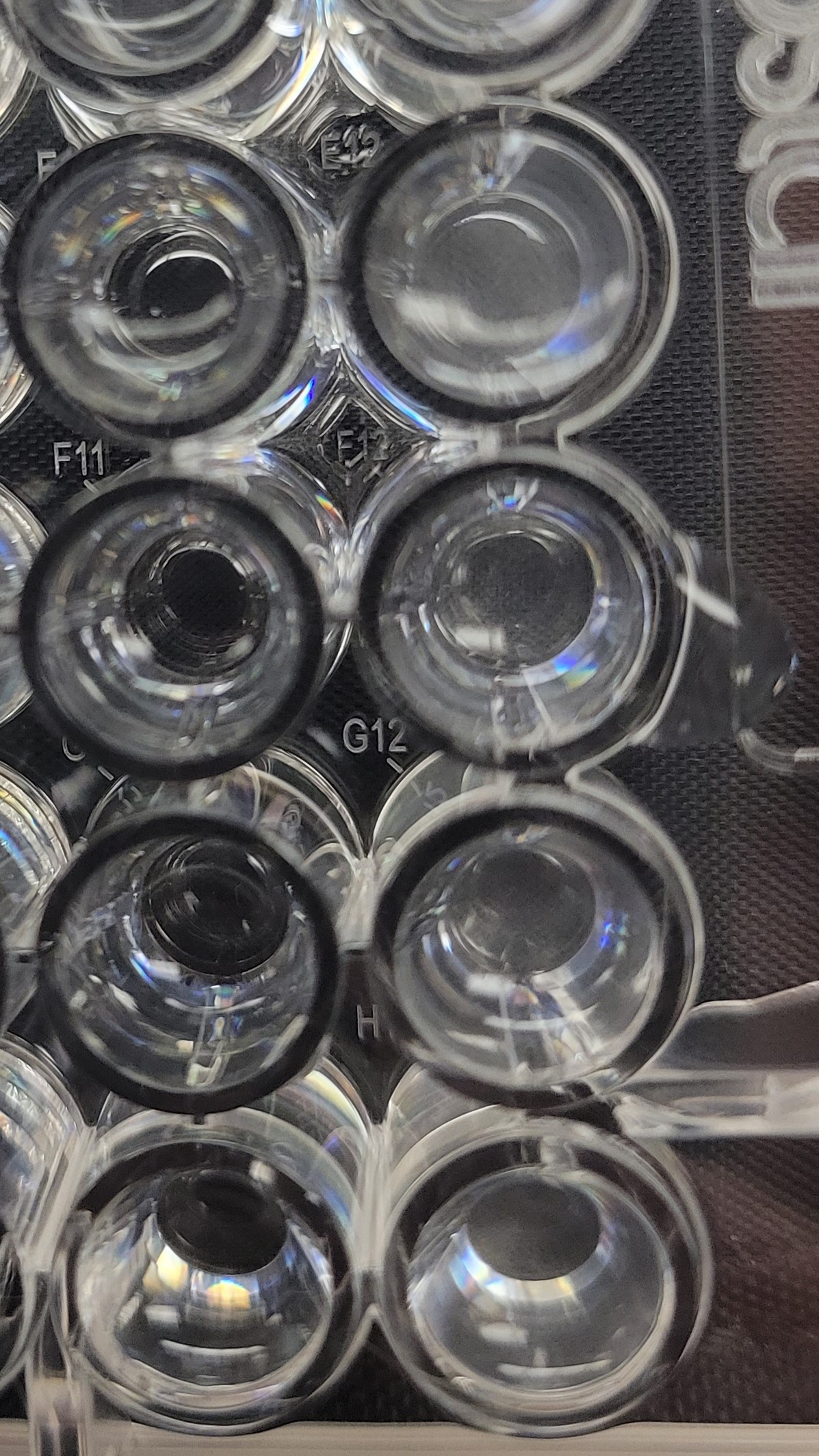
Figure 5: Results (White bead outflow on the right wells, pure solvent outflow on the left wells)